Apollo 11 mission reconstruction - a teamwork

Post requests, images, descriptions and reports about work in progress here.
Topic author
ElChristou
Developer
Posts: 3776
Joined: 04.02.2005
With us: 19 years 9 months

Post #221by ElChristou » 16.08.2007, 15:46

ANDREA wrote:...But sincerely at this point I have not clear what exactly you are actually missing.
Could you be more detailed, please? :wink:
Tks...


Ok; I think that at his point we have a good idea of the structure, the several elements etc.
Now, the main problem in 3D, is that you are facing... 3D! You must analyze several docs to determinate the right proportion of things, but most important if you want your model accurate, their function. For this the best are of course blue prints...

Let's take the example of this last 360?° SLA. Ok, we have here the placement and an approximate idea of the shape of all elements. Now, to open the SLA, I need to know how was done the LM attach Fairing for example, but this doc is not useful for this. In this case I must dig in many pdf or real shots to reconstruct the puzzle...

In the absolute for a good model, we need general shots (to determinate general shape and placements of details), and close up shots of ALL those details. If we can find blue prints, better, but in reality, if we had enough shots (during assembly for example) it would be enough.

The main problem is that in general we can find quickly one or two details, but regrouping ALL the necessary information is a real challenge... (It's why the team job is preferred here).
Image

ANDREA
Posts: 1543
Joined: 01.06.2002
With us: 22 years 5 months
Location: Rome, ITALY

Post #222by ANDREA » 16.08.2007, 17:33

ElChristou wrote:
ANDREA wrote:...But sincerely at this point I have not clear what exactly you are actually missing. Could you be more detailed, please? :wink: Tks...(It's why the team job is preferred here).
Ok; I think that at his point we have a good idea of the structure, the several elements etc. Now, the main problem in 3D, is that you are facing... 3D! You must analyze several docs to determinate the right proportion of things, but most important if you want your model accurate,
their function. For this the best are of course blue prints... Let's take the example of this last 360?° SLA. Ok, we have here the placement and an approximate idea of the shape of all elements. Now, to open the SLA, I need to know how was done the LM attach Fairing for example, but this doc is not useful for this. In this case I must dig in many pdf or real shots to reconstruct the puzzle...

Well, I understand what you mean and what you need, but surely many details are not available, or at least will need much more time/effort to be found.
Anyhow, I digged in many pdf for the LM attachment system, and here are the results:

Image

Image

Image

You can find the bigger original here:
http://ftp.tiscali.it/andrea_celestia/L ... -ad018.jpg

Image

Image

In practice the LM was attached by its legs to the SLA fixed ring, with explosive bolts.
Nice to understand things! :wink:
In the next image you can see how SLA panels hinges worked,

Image

And here a dedicated link with many interesting drawings:
http://www.adboo.com/cmnr/spacecraftlmadapter.htm

Bye soon

Andrea :D
"Something is always better than nothing!"
HP Omen 15-DC1040nl- Intel® Core i7 9750H, 2.6/4.5 GHz- 1TB PCIe NVMe M.2 SSD+ 1TB SATA 6 SSD- 32GB SDRAM DDR4 2666 MHz- Nvidia GeForce GTX 1660 Ti 6 GB-WIN 11 PRO

Topic author
ElChristou
Developer
Posts: 3776
Joined: 04.02.2005
With us: 19 years 9 months

Post #223by ElChristou » 16.08.2007, 18:05

Cool, some more piece of the puzzle. Ok, let's take a break with the search, I have many new sources to dig in, so I'll go for more modeling and let you know a bit later if something is missing.
Image

ANDREA
Posts: 1543
Joined: 01.06.2002
With us: 22 years 5 months
Location: Rome, ITALY

Post #224by ANDREA » 16.08.2007, 21:48

D'accord comme ?§a, mon capitaine. :wink:
Bye

Andrea :D
"Something is always better than nothing!"
HP Omen 15-DC1040nl- Intel® Core i7 9750H, 2.6/4.5 GHz- 1TB PCIe NVMe M.2 SSD+ 1TB SATA 6 SSD- 32GB SDRAM DDR4 2666 MHz- Nvidia GeForce GTX 1660 Ti 6 GB-WIN 11 PRO

Topic author
ElChristou
Developer
Posts: 3776
Joined: 04.02.2005
With us: 19 years 9 months

Post #225by ElChristou » 16.08.2007, 22:24

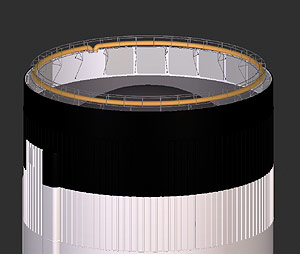
Begining the IU...

What's the hell is the IU?

Taken from the sa503-flightmanual:

Code: Select all

The Instrumnent Unit (IU) is a cylindrical structure installed on top of the S-IVB stage [...]. The IU contains the guidance, navigation, and control equipment which will guide the vehicle through its earth orbits and subsequently into its mission trajectory. In addition, it contains telemetry, communications, tracking, and crew safety systems, along
with their supporting electrical power and enviromnental control systems.


(Click to enlarge)

Image
Image

ANDREA
Posts: 1543
Joined: 01.06.2002
With us: 22 years 5 months
Location: Rome, ITALY

Post #226by ANDREA » 16.08.2007, 22:58

ElChristou wrote:Begining the IU...
What's the hell is the IU?
Taken from the sa503-flightmanual:

Code: Select all

The Instrumnent Unit (IU) is a cylindrical structure installed on top of the S-IVB stage [...]. The IU contains the guidance, navigation, and control equipment which will guide the vehicle through its earth orbits and subsequently into its mission trajectory. In addition, it contains telemetry, communications, tracking, and crew safety systems, along
with their supporting electrical power and enviromnental control systems.

As you see it's the ring that links stage S-IV to the SLA.
It contains tons of electronics, all the stuff needed to command all Saturn components.
I've a lot of very detailed drawings, but I didn't give you them because the details are all internal, practically nothing externally.
If you need them, anyhow, I can show them in a veeery short time. :wink:
Here a preview:

Image

Image

And here the document contatining detailed drawings of all the internal ring instruments on IU
http://ftp.tiscali.it/andrea_celestia/A ... nVInfo.pdf (pay attention, it's 10 MB).
If you need them I've some images, too.
Enjoy!
Bye

Andrea :D
"Something is always better than nothing!"
HP Omen 15-DC1040nl- Intel® Core i7 9750H, 2.6/4.5 GHz- 1TB PCIe NVMe M.2 SSD+ 1TB SATA 6 SSD- 32GB SDRAM DDR4 2666 MHz- Nvidia GeForce GTX 1660 Ti 6 GB-WIN 11 PRO

Topic author
ElChristou
Developer
Posts: 3776
Joined: 04.02.2005
With us: 19 years 9 months

Post #227by ElChristou » 16.08.2007, 23:27

ANDREA wrote:...If you need them, anyhow, I can show them in a veeery short time...


I think the pdf is enough; I do need to model the inner part because once the LEM is out one will be able to see it... (I'll try to do it as light as possible, else I will never be able to run the addon on my config! :x)
Image

ANDREA
Posts: 1543
Joined: 01.06.2002
With us: 22 years 5 months
Location: Rome, ITALY

Post #228by ANDREA » 16.08.2007, 23:41

ElChristou wrote:
ANDREA wrote:...If you need them, anyhow, I can show them in a veeery short time...
I think the pdf is enough; I do need to model the inner part because once the LEM is out one will be able to see it... (I'll try to do it as light as possible, else I will never be able to run the addon on my config! :x)

OK, but for this purpose I think this image can be of help:

Image

Do you agree?
Bye

Andrea :D
"Something is always better than nothing!"
HP Omen 15-DC1040nl- Intel® Core i7 9750H, 2.6/4.5 GHz- 1TB PCIe NVMe M.2 SSD+ 1TB SATA 6 SSD- 32GB SDRAM DDR4 2666 MHz- Nvidia GeForce GTX 1660 Ti 6 GB-WIN 11 PRO

Topic author
ElChristou
Developer
Posts: 3776
Joined: 04.02.2005
With us: 19 years 9 months

Post #229by ElChristou » 16.08.2007, 23:49

Arrgg... this mean the circular structure is covered with a kind of protection!?

Mhhmm... to verify this we need a view where we can see the inner part of the IU during the LEM extraction...

Do you remember a shot like this?
Image

ANDREA
Posts: 1543
Joined: 01.06.2002
With us: 22 years 5 months
Location: Rome, ITALY

Post #230by ANDREA » 17.08.2007, 00:06

ElChristou wrote:Arrgg... this mean the circular structure is covered with a kind of protection!?
Mhhmm... to verify this we need a view where we can see the inner part of the IU during the LEM extraction...
Do you remember a shot like this?

The reply is, sorry, yes for both questions!
And here is the image that confirms it:

Image

Bye, going to sleep. :wink:

Andrea :D
"Something is always better than nothing!"
HP Omen 15-DC1040nl- Intel® Core i7 9750H, 2.6/4.5 GHz- 1TB PCIe NVMe M.2 SSD+ 1TB SATA 6 SSD- 32GB SDRAM DDR4 2666 MHz- Nvidia GeForce GTX 1660 Ti 6 GB-WIN 11 PRO

Topic author
ElChristou
Developer
Posts: 3776
Joined: 04.02.2005
With us: 19 years 9 months

Post #231by ElChristou » 17.08.2007, 00:57

ANDREA wrote:...And here is the image that confirms it:...


In fact this shot don't really confirm it; as many protections are used during assembly, the only way to be really sure is a shot during flight... If you look closely the CSM, there is still some missing element of the skirt, so it was probably a test assembly, nothing definitive. Or perhaps it's not an assembly at all, just the viewpoint faking the impression! 8O :wink:

In all case, it would be better to have this protection (-> less poly), but before deleting the useless meshes I've done, let's wait further docs, who knows...

I'll continue with the electronic.
Image

ANDREA
Posts: 1543
Joined: 01.06.2002
With us: 22 years 5 months
Location: Rome, ITALY

Post #232by ANDREA » 17.08.2007, 08:21

ElChristou wrote:
ANDREA wrote:...And here is the image that confirms it:...
In fact this shot don't really confirm it; as many protections are used during assembly, the only way to be really sure is a shot during flight... If you look closely the CSM, there is still some missing element of the skirt, so it was probably a test assembly, nothing definitive. Or perhaps it's not an assembly at all, just the viewpoint faking the impression! 8O :wink:
In all case, it would be better to have this protection (-> less poly), but before deleting the useless meshes I've done, let's wait further docs, who knows...I'll continue with the electronic.

Last message's image caption says:
"Apollo spacecraft 103 is mated to instrument unit atop SA-503 Apollo 8, October 7, 1968", and Apollo 8 flight was on October 9, 1968, so the flight configuration could have the cover.
But next image

Image

says "Engineers are dwarfed as the Apollo 9 command, service and lunar modules are mated to Apollo/Saturn V space vehicle's instrument unit. December 5, 1968", and this time the Apollo flight was on Mar 3, 1969, more than three months later, so this is doubtfull.
This one, almost identical,

Image

says "Apollo 17 spacecraft is gently lowered down atop the Instrument Unit during mating operations, August 24, 1972", and once again the flight was on Dec 7, 1972, more than three months later.
You are right, we need more information. :cry:
Anyhow I have the feeling that the cover was left up to final installation, where it was removed, shoving now the bundle of electric/electronic cables shown in both images, and the following one

Image

could give the proof of this, IMHO. 8O
BTW, the IU was produced by IBM.
Digging more.
Bye

Andrea :D
"Something is always better than nothing!"
HP Omen 15-DC1040nl- Intel® Core i7 9750H, 2.6/4.5 GHz- 1TB PCIe NVMe M.2 SSD+ 1TB SATA 6 SSD- 32GB SDRAM DDR4 2666 MHz- Nvidia GeForce GTX 1660 Ti 6 GB-WIN 11 PRO

Topic author
ElChristou
Developer
Posts: 3776
Joined: 04.02.2005
With us: 19 years 9 months

Post #233by ElChristou » 17.08.2007, 11:29

I'm wondering how big (or small) would be the same electronic devices today... The gain in room and weight should be enormous... 8O
Image

ANDREA
Posts: 1543
Joined: 01.06.2002
With us: 22 years 5 months
Location: Rome, ITALY

Post #234by ANDREA » 17.08.2007, 12:22

ElChristou wrote:I'm wondering how big (or small) would be the same electronic devices today... The gain in room and weight should be enormous... 8O

Well, look at this info, regarding the Apollo Guidance Computer:

Instruction Set: Approximately 20 instructions;
100 noun-verb pairs, data up to triple-precision
Word Length: 16 bits (14 bits + sign + parity)
Memory: ROM (rope core) 36K words; RAM (core) 2K words 8O
Disk: None
I/O: DSKY (two per spacecraft)
Performance: approx. Add time - 20us
Basic machine cycle: 2.048 MHz
Technology: RTL bipolar logic (flat pack)
Size: AGC - 24" x 12.5" x 6" (HWD); DSKY - 8" x 8" x 7" (HWD)
Weight: AGC - 70 lbs; DSKY - 17.5 lbs 8O
Number produced: AGC - 75; DSKY: 138
Cost: Unknown.
Power consumption: Operating: 70W @ 28VDC; Standby 15.0 watts


Any today's 300 US$ PC exceeds this a tenfold times at least, with a 1/100th weight. 8O
But remember that 40 years are a very big leap in technology.
Bye

Andrea :D
"Something is always better than nothing!"
HP Omen 15-DC1040nl- Intel® Core i7 9750H, 2.6/4.5 GHz- 1TB PCIe NVMe M.2 SSD+ 1TB SATA 6 SSD- 32GB SDRAM DDR4 2666 MHz- Nvidia GeForce GTX 1660 Ti 6 GB-WIN 11 PRO

Avatar
selden
Developer
Posts: 10192
Joined: 04.09.2002
With us: 22 years 2 months
Location: NY, USA

Post #235by selden » 17.08.2007, 13:15

Of course, space-qualified computers have features that are not available in most consumer-grade computers. Like radiation hardening and the ability to work in a vacuum.
Selden

ANDREA
Posts: 1543
Joined: 01.06.2002
With us: 22 years 5 months
Location: Rome, ITALY

Post #236by ANDREA » 17.08.2007, 13:58

selden wrote:Of course, space-qualified computers have features that are not available in most consumer-grade computers. Like radiation hardening and the ability to work in a vacuum.

Selden, obviously I agree with you, but can you imagine a today's computer with similar features?
Wouldn't it be anyway A LOT more powerful AND lighter in weight?
I think yes, don't you? :wink:
Bye

Andrea :D
"Something is always better than nothing!"
HP Omen 15-DC1040nl- Intel® Core i7 9750H, 2.6/4.5 GHz- 1TB PCIe NVMe M.2 SSD+ 1TB SATA 6 SSD- 32GB SDRAM DDR4 2666 MHz- Nvidia GeForce GTX 1660 Ti 6 GB-WIN 11 PRO

ANDREA
Posts: 1543
Joined: 01.06.2002
With us: 22 years 5 months
Location: Rome, ITALY

Post #237by ANDREA » 17.08.2007, 14:30

Here two close-ups of the IU during construction:

Image

Image

I present these images because the shape of the cover is more clear: it was in 24 separate sections, the same shown in the first image in this page, that could be rotated externally in order to show and access the wirings.
In the first image you can see some of the removed covers lying on the floor, internally to the IU.
Very strange. 8O
IMHO this gives more points to the possibility that the covers were left during construction and tests, and eliminated just before the SLA final link. :wink:
However we still need a confirmation. :cry:
Bye

Andrea :D
"Something is always better than nothing!"
HP Omen 15-DC1040nl- Intel® Core i7 9750H, 2.6/4.5 GHz- 1TB PCIe NVMe M.2 SSD+ 1TB SATA 6 SSD- 32GB SDRAM DDR4 2666 MHz- Nvidia GeForce GTX 1660 Ti 6 GB-WIN 11 PRO

Boux
Posts: 435
Joined: 25.08.2004
With us: 20 years 3 months
Location: Brittany, close to the Ocean

Post #238by Boux » 17.08.2007, 18:54

Don't worry about simplifying your model.
These rigid foam looking "covers" are mere protections during the assembly phase of the instrument unit. They are to be removed before final assembly - and launch, obviously.
Old souvenirs from the Ariane launcher.
The IU is called "case ?  ?©quipements" in French. Very similar to this stuff.
It is standard on most if not all launchers, in one form or another.
The other pieces of metal across the IU on one of the pics are likely just meant to rigidify the structure during handling and keep it within tolerances.
You have to realize that all these pieces of structure are made as lightweight as possible and are very fragile. Every part gets its final rigidity from the assembly of the whole system.
Also, don't be worried about the apparent long time elapsed between some shots. There are many quality control operations and procedures at every step of the construction. These can span over months.
Good construction! :D
Intel core i7 3770 Ivy Bridge @ 4.4 GHz -16 GB ram - 128 GB SSD cache - AMD Radeon 7970 3 GB o'clocked - Windows 7 64 Ultimate / Linux Kubuntu

Topic author
ElChristou
Developer
Posts: 3776
Joined: 04.02.2005
With us: 19 years 9 months

Post #239by ElChristou » 17.08.2007, 19:31

Boux wrote:Don't worry about simplifying your model.
These rigid foam looking "covers" are mere protections during the assembly phase of the instrument unit. They are to be removed before final assembly - and launch, obviously.
Old souvenirs from the Ariane launcher....


Ok, then more work for me! :wink:

So you have been working on Ariane?
Image

ANDREA
Posts: 1543
Joined: 01.06.2002
With us: 22 years 5 months
Location: Rome, ITALY

Post #240by ANDREA » 17.08.2007, 21:11

Boux wrote:Don't worry about simplifying your model.
These rigid foam looking "covers" are mere protections during the assembly phase of the instrument unit. They are to be removed before final assembly - and launch, obviously.
Old souvenirs from the Ariane launcher.
The IU is called "case ?  ?©quipements" in French. Very similar to this stuff.
It is standard on most if not all launchers, in one form or another...Also, don't be worried about the apparent long time elapsed between some shots. There are many quality control operations and procedures at every step of the construction. These can span over months.
Good construction! :D

Thank you Boux for the precious information, appreciated.
So I was right when I was saying:
    Anyhow I have the feeling that the cover was left up to final installation, where it was removed, shoving now the bundle of electric/electronic cables
This means that now Chris has all the information needed to realize the IU. :wink:
Well done, thank you again.
Bye

Andrea :D
"Something is always better than nothing!"
HP Omen 15-DC1040nl- Intel® Core i7 9750H, 2.6/4.5 GHz- 1TB PCIe NVMe M.2 SSD+ 1TB SATA 6 SSD- 32GB SDRAM DDR4 2666 MHz- Nvidia GeForce GTX 1660 Ti 6 GB-WIN 11 PRO


Return to “Add-on development”