NEW Voyager model...

Post requests, images, descriptions and reports about work in progress here.
Topic author
ElChristou
Developer
Posts: 3776
Joined: 04.02.2005
With us: 19 years 7 months

Post #21by ElChristou » 24.06.2006, 20:43

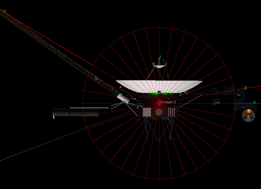
Fightspit wrote:Just a question: Why your antena is not really smooth (c'est a dire lisse :lol:) ?


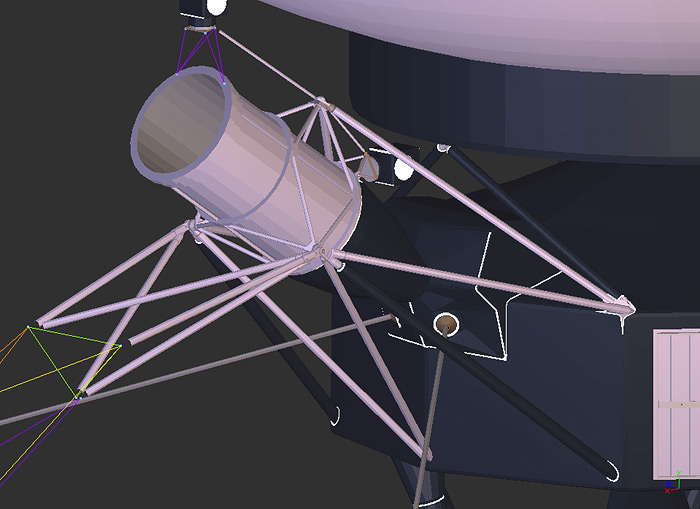
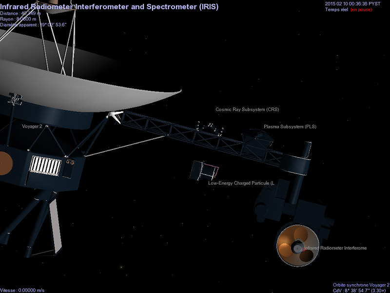
Because it's a flat OpenGL rendering in my 3D soft; on the third pict on previous page, you can see a Celestia rendering where the dish is smoothed...
Image

Topic author
ElChristou
Developer
Posts: 3776
Joined: 04.02.2005
With us: 19 years 7 months

Post #22by ElChristou » 24.06.2006, 23:34

Pfff... the big part of the tubes is ready :D

Image
Image

Vincent
Developer
Posts: 1356
Joined: 07.01.2005
With us: 19 years 8 months
Location: Nancy, France

Post #23by Vincent » 25.06.2006, 10:24

8O Amazing ! BRAVO Chris !! :D
@+
Vincent

Celestia Qt4 SVN / Celestia 1.6.1 + Lua Edu Tools v1.2
GeForce 8600 GT 1024MB / AMD Athlon 64 Dual Core / 4Go DDR2 / XP SP3

osmium
Posts: 70
Joined: 16.07.2004
With us: 20 years 2 months

Post #24by osmium » 25.06.2006, 11:28

That is some really nice work! 8O :D :D :D :o :P

cheers

Os.
Under the bonnet..
Win XP home ed SP2
512 MB RAM
80.0 GB HD
RADEON 9700 PRO display Adapter.
AMD Athlon 2600+
Celestia 1.4.1

Topic author
ElChristou
Developer
Posts: 3776
Joined: 04.02.2005
With us: 19 years 7 months

Post #25by ElChristou » 25.06.2006, 11:50

Tx guys!
Image

Topic author
ElChristou
Developer
Posts: 3776
Joined: 04.02.2005
With us: 19 years 7 months

Post #26by ElChristou » 26.06.2006, 16:15

Image

Franck,

Those are the points where I need more details; in 3, the attach system; in 4 various angles if possible; in 5 the attach points + the articulation in the middle; in 6 and 7 (Cosmic ray and Low energy charged particules detector), various angles; in 8 several shots, principally from this point of view, more details on the photopolarimeter and the UV spectrometer.

In general, a few shots of this side of the spacecraft are welcome.

Concerning the RTG, there is a sort of "cap" at the very end, here also some shots.

Concerning the boom, I think there is something in the middle but have no docs to confirm it... more shots? :wink:
Image

Avatar
fsgregs
Posts: 1307
Joined: 07.10.2002
With us: 21 years 11 months
Location: Manassas, VA

Post #27by fsgregs » 27.06.2006, 01:13

Chris:

I've printed out the image above and will do my best.

Frank

Topic author
ElChristou
Developer
Posts: 3776
Joined: 04.02.2005
With us: 19 years 7 months

Post #28by ElChristou » 27.06.2006, 01:45

fsgregs wrote:Chris:

I've printed out the image above and will do my best.

Frank


Tx! with that, this model will be very accurate!! :D
Image

Topic author
ElChristou
Developer
Posts: 3776
Joined: 04.02.2005
With us: 19 years 7 months

Post #29by ElChristou » 28.06.2006, 16:02

Guys, I met a problem...
I have the idea to create several entries to point on the different instruments to make the visualization easier...
I was supposing that with a double of the Voyager declaration (pointing to a fake 3DS) and a modification of the mesh center I could get it... but nope... here the ssc:

Code: Select all

"Voyager 2" "Sol"

{

Class         "spacecraft"
Mesh         "voyager.3ds" 
Radius         0.019
MeshCenter      [ -0.2805 0 -0.175 ]

Beginning      "1977 8 20 12:00"   #Launch # Ending ???

SampledOrbit      "voyager2.xyz"

EllipticalOrbit
{
Period         8.054860
SemiMajorAxis      4.018266
Eccentricity      6.284578
Inclination      78.810177
AscendingNode      100.934989
ArgOfPericenter      130.043962
MeanAnomaly      342.970736
Epoch         2448257.5
}

Albedo         0.1
RotationPeriod      100000

}

"Voyager: Plasma Subsystem (PLS)" "Sol"

{
Class         "spacecraft"
Mesh         "z.3ds" 
Radius         0.006

MeshCenter      [ -0.55 0 -0.15 ]

Beginning      "1977 8 20 12:00"   #Launch # Ending ???

SampledOrbit      "voyager2.xyz"
       
EllipticalOrbit
{
Period         8.054860
SemiMajorAxis      4.018266
Eccentricity      6.284578
Inclination      78.810177
AscendingNode      100.934989
ArgOfPericenter      130.043962
MeanAnomaly      342.970736
Epoch         2448257.5
}

Albedo         0.1
RotationPeriod      100000

}


What is really weird is that the change in the MeshCenter don't work, the marker for the PLS still in place of the Voyager marker... Any idea of what's wrong?
Image

Avatar
selden
Developer
Posts: 10190
Joined: 04.09.2002
With us: 22 years
Location: NY, USA

Post #30by selden » 28.06.2006, 16:21

When you have both SampledOrbit and EllipticalOrbit defined only the SampledOrbit is used. You might want to delete the unused orbit definition in order to avoid confusion.

I've never understood how MeshCenter works.

It'll probably be easier if you use the LongLat declaration to define locations relative to the primary object.

e.g.

Code: Select all

"SpaceProbe" "Sol" { ...EllipticalOrbit{...}... }

"Component" "Sol/SpaceProbe" {
   ...
    LongLat [ 120 50 0.001 ]
   ...
 }
Selden

Topic author
ElChristou
Developer
Posts: 3776
Joined: 04.02.2005
With us: 19 years 7 months

Post #31by ElChristou » 28.06.2006, 16:33

selden wrote:When you have both SampledOrbit and EllipticalOrbit defined only the SampledOrbit is used. You might want to delete the unused orbit definition in order to avoid confusion.

Damned indeed... well this was the original ssc from Jack Higgins, I though I could not have to put my hands in there... but I was wrong... :wink:


selden wrote:I've never understood how MeshCenter works.

It'll probably be easier if you use the LongLat declaration to define locations relative to the primary object.

e.g.

Code: Select all

"SpaceProbe" "Sol" { ...EllipticalOrbit{...}... }

"Component" "Sol/SpaceProbe" {
   ...
    LongLat [ 120 50 0.001 ]
   ...
 }


Ok, Tx Selden, I'll test this.
Image

Topic author
ElChristou
Developer
Posts: 3776
Joined: 04.02.2005
With us: 19 years 7 months

Post #32by ElChristou » 28.06.2006, 18:30

The lenght of the name of an object is limited !? :x
Is there a way to fix this?

Image
Image

Fightspit
Posts: 510
Joined: 15.05.2005
With us: 19 years 4 months

Post #33by Fightspit » 28.06.2006, 18:39

Try to put the longest french word "anticonstitutionnellement", just to see :wink:
Motherboard: Intel D975XBX2
Processor: Intel Core2 E6700 @ 3Ghz
Ram: Corsair 2 x 1GB DDR2 PC6400
Video Card: Nvidia GeForce 8800 GTX 768MB GDDR3 384 bits PCI-Express 16x
HDD: Western Digital Raptor 150GB 10000 rpm
OS: Windows Vista Business 32 bits

Topic author
ElChristou
Developer
Posts: 3776
Joined: 04.02.2005
With us: 19 years 7 months

Post #34by ElChristou » 29.06.2006, 01:46

Searching how to avoid the restricted length for object's name, I tested with Location; here the length is not a problem anymore but...

Does Celestia can do collision detection????

I met a strange behavior in placing the locations, so I done the following test:

Loc A is at [ 10 0 0 ],
Loc B at [ 20 0 0 ],
Loc C at [ 30 0 0 ] etc...

Here the result; I have overlay a circle divided every 10 degrees and effectively the labels are positioned along those lines... what I don't understand is how Celestia determinate where the labels is on those lines... seems that the labels are positioned at the intersection of the lines with the meshes... so collision detection?

Image
Image

buggs_moran
Posts: 835
Joined: 27.09.2004
With us: 20 years
Location: Massachusetts, USA

Post #35by buggs_moran » 29.06.2006, 02:20

Could it have something to do with lat-long being interpreted for a sphere and not a complex shape like Voyager?
Homebrew:
WinXP Pro SP2
Asus A7N8X-E Deluxe
AMD Athlon XP 3000/333 2.16 GHz
1 GB Crucial RAM
80 GB WD SATA drive
ATI AIW 9600XT 128M

buggs_moran
Posts: 835
Joined: 27.09.2004
With us: 20 years
Location: Massachusetts, USA

Post #36by buggs_moran » 29.06.2006, 02:51

Also found these...

LECP *which I believe is #7 on your diagram for Frank
http://hurlbut.jhuapl.edu/VOYAGER/lecp_jpg.html
http://hurlbut.jhuapl.edu/VOYAGER/tech_ ... l_1999.pdf


Frank, you might like this. I might give it a try this year.
http://voyager.jpl.nasa.gov/pdf/VoyagerPosterFinal2.pdf
Homebrew:

WinXP Pro SP2

Asus A7N8X-E Deluxe

AMD Athlon XP 3000/333 2.16 GHz

1 GB Crucial RAM

80 GB WD SATA drive

ATI AIW 9600XT 128M

Avatar
selden
Developer
Posts: 10190
Joined: 04.09.2002
With us: 22 years
Location: NY, USA

Post #37by selden » 29.06.2006, 11:38

Code: Select all

"Object" "Sol" { Radius 1.0  EllipticalOrbit {...} }

"Component" "Sol/Object" {
LongLat [ <longitude> <latitude> <altitude> ]
}


Longitude and Latitude are defined to be on a sphere at the specified Altitude.

Altitude is distance from the surface of "Object". That surface is is a sphere defined by the Radius of Object. The Altitude is not measured with respect to the shape of whatever Mesh you might be using.
Selden

buggs_moran
Posts: 835
Joined: 27.09.2004
With us: 20 years
Location: Massachusetts, USA

Post #38by buggs_moran » 29.06.2006, 11:41

Then Chris' problem is really strange since the objects seem to stop at intersection with the model in some cases... perhaps because of the 0 as altitude the locations stop at the model.
Homebrew:

WinXP Pro SP2

Asus A7N8X-E Deluxe

AMD Athlon XP 3000/333 2.16 GHz

1 GB Crucial RAM

80 GB WD SATA drive

ATI AIW 9600XT 128M

Avatar
selden
Developer
Posts: 10190
Joined: 04.09.2002
With us: 22 years
Location: NY, USA

Post #39by selden » 29.06.2006, 11:55

Although it isn't perfect, Celestia does depth sorting for labels and opaque surfaces.
Selden

Topic author
ElChristou
Developer
Posts: 3776
Joined: 04.02.2005
With us: 19 years 7 months

Post #40by ElChristou » 29.06.2006, 12:35

selden wrote:Longitude and Latitude are defined to be on a sphere at the specified Altitude.

Altitude is distance from the surface of "Object". That surface is is a sphere defined by the Radius of Object. The Altitude is not measured with respect to the shape of whatever Mesh you might be using.


It's exactly what I was expecting... but nope, I get the Locs following the meshes, it's why I was asking for collision detection... perhaps it's a bug, but it can be a very good one!!

The main problem in this case is that the scale of altitude change for each point (proportional to their distance to the center of the model)... so it's a bit tricky to find out the good settings for each Locs...
Image


Return to “Add-on development”