
Blue Venus Parasol & Reflector (Mega Structures)
-
ElChristou
- Developer
- Posts: 3776
- Joined: 04.02.2005
- With us: 20 years 2 months
selden wrote:For what it's worth, I had no problems reading the L1 parasol 3DS file using Anim8or (a freeware Windows 3D design program). It took while to read the file, but I was even able to export it to CMOD format, too.
I'm sure it's a problem of resources; the app sems to hang on but no, they just need a looong time to load the model... Anyway such model is not a very very good solution...

ElChristou wrote:selden wrote:For what it's worth, I had no problems reading the L1 parasol 3DS file using Anim8or (a freeware Windows 3D design program). It took while to read the file, but I was even able to export it to CMOD format, too.
I'm sure it's a problem of resources; the app sems to hang on but no, they just need a looong time to load the model... Anyway such model is not a very very good solution...
I guarantee it has more to do with resources then the model itself being bad. if i load up the original DWG file it consumes over 1.5GB. Using strangely enough the 3ds file only consumes about 200MB using Deep Exploration. I think its all how the modeler hands object in memory. Anyway Instead of me giving everyone a huge monolithic item, lets see if there is a better way create the model by concentrating on only specific areas on the model.
Enhancements for Celestia
http://www.celestiamotherlode.net/
http://www.celestialmatters.org/
Development Road Map
http://en.wikibooks.org/wiki/Celestia/D ... t_Road_Map
http://www.celestiamotherlode.net/
http://www.celestialmatters.org/
Development Road Map
http://en.wikibooks.org/wiki/Celestia/D ... t_Road_Map
-
eburacum45
- Posts: 691
- Joined: 13.11.2003
- With us: 21 years 4 months
This is the parasol and mirror model I use in OA; it is a very simple model, a semitransparent disk with some opaque detailing. I suppose it doesn't really give the impression of size (of course this is a very foreshortened image).
Venus also has statite mirrors and a dynamic orbital ring (well, there was a lot of carbon to get rid of, so they simply used some of it in orbit to build another megastructure)

Venus also has statite mirrors and a dynamic orbital ring (well, there was a lot of carbon to get rid of, so they simply used some of it in orbit to build another megastructure)

-
ElChristou
- Developer
- Posts: 3776
- Joined: 04.02.2005
- With us: 20 years 2 months
MKruer wrote:...lets see if there is a better way create the model by concentrating on only specific areas on the model.
The main problem of a simple dish with a texture is relative to the edges; how do you imagine the edges should be?
Like on you shots? (or that's just because the model is not over?)
Last edited by ElChristou on 12.11.2007, 16:26, edited 1 time in total.
-
chris
- Site Admin
- Posts: 4211
- Joined: 28.01.2002
- With us: 23 years 2 months
- Location: Seattle, Washington, USA
Reference frames in 1.5.0 are the ideal way to place objects in Lagrange points. This example places spheres at Earth's L1 and L2 points:
The objects are placed at fixed points within a reference frame that rotates as the Earth revolves around the Sun. It should be easy to adapt this for Venus--just change Earth to Venus, and adjust the FixedPositions with realistic values for Venus. The L1, L2, and L3 points are all unstable, but there do exist stable orbits about points. As Selden mentioned, such orbits can be simulated with a ScriptedOrbit, but even placing the mirrors in a fixed location right at the Lagrange points is a big step in the right direction.
--Chris
Code: Select all
"L1" "Sol/Earth"
{
    Radius 4000
    Color [ 1 0 0 ]

    OrbitFrame {
         TwoVector {
            Center "Sol/Earth"
            Primary {
                Axis "x"
                RelativePosition { Target "Sol" }
            }
            Secondary {
                Axis "y"
      RelativeVelocity { Target "Sol" }
            }
        }
    }

    FixedPosition [ 1500000 0 0 ]
}

"L2" "Sol/Earth"
{
    Radius 4000
    Color [ 1 0 0 ]

    OrbitFrame {
         TwoVector {
            Center "Sol/Earth"
            Primary {
                Axis "x"
                RelativePosition { Target "Sol" }
            }
            Secondary {
                Axis "y"
      RelativeVelocity { Target "Sol" }
            }
        }
    }

    FixedPosition [ -1500000 0 0 ]
}
The objects are placed at fixed points within a reference frame that rotates as the Earth revolves around the Sun. It should be easy to adapt this for Venus--just change Earth to Venus, and adjust the FixedPositions with realistic values for Venus. The L1, L2, and L3 points are all unstable, but there do exist stable orbits about points. As Selden mentioned, such orbits can be simulated with a ScriptedOrbit, but even placing the mirrors in a fixed location right at the Lagrange points is a big step in the right direction.
--Chris
-
eburacum45
- Posts: 691
- Joined: 13.11.2003
- With us: 21 years 4 months
One sensible design for such a parasol would be a Fresnel lens, which would disperse the sunlight rather than reflect it. This would decrease the solar sail effect which tends to move the shade towards Venus. I suppose the lens could even focus some of the light onto the statite mirrors.
Recent ideas for creating such a shade have described a swarm, rather than a single object- but unless the swarm is carefully controlled, I think it will eventually coalesce into lumps.
Recent ideas for creating such a shade have described a swarm, rather than a single object- but unless the swarm is carefully controlled, I think it will eventually coalesce into lumps.
First of all thank you to everyone. This has generated more interest then I originally though, and I appreciate the feed back.
ElChristou I think the way I could do it would be by creating two models. The first one would be a detailed model that would represent all the sub tiles that could be selected in and zoom upon, but of over all structure would be a simple 2d model. As someone pointed out its unlikely that anyone would look in detail over each part, so I could just use a repetitious image to fake the rest. This should drop the poly count tremendously. I can create the smaller structure, but I will need help creating the over all structure.
eburacum45 I took a look at various methods, including the swarm, and I came up with what I believe would be the best over all design. Each structure is crearted of smaller sub tiles. Each tile would be its own unit, but each unit would be connected at the corners by a sort of universal joint that allows for some wiggle room. Both mega structures would be concave in over all design. The reason for this is to allow the radiation pressure to push the object apart. Because each tile can be opened and closed to create the night/day cycle, one could balance the pressure over the entire object to keep the structures in constant tension (it?€™s vastly easer to make the structure thin and flimsy but with held together with tension then to make a ridged structure and held together via tensile strength.) At least this is the conclusion I came to.
Using Chris method, I now have the correct positions of the Parasol and Reflector

cel://SyncOrbit/Sol:Venus/2008-01-11T01 ... enus:Venus Parasol (L1)&fov=41.116798&ts=1.000000<d=0&rf=2168295&lm=2054&ver=2
Code: Select all
"Venus Parasol (L1)" "Sol/Venus"
{
   Mesh   "L1_Venus_Parasol.3ds"
   Radius   12715

    OrbitFrame {
         TwoVector {
            Center "Sol/Venus"
            Primary {
                Axis "x"
                RelativePosition { Target "Sol" }
            }
            Secondary {
                Axis "y"
      RelativeVelocity { Target "Sol" }
            }
        }
    }

    FixedPosition [ 1004392 0 0 ]
}

"Venus Reflector (L2)" "Sol/Venus"
{
   Mesh   "L2_Venus_Reflector.3ds"
   Radius   19050

    OrbitFrame {
         TwoVector {
            Center "Sol/Venus"
            Primary {
                Axis "x"
                RelativePosition { Target "Sol" }
            }
            Secondary {
                Axis "y"
      RelativeVelocity { Target "Sol" }
            }
        }
    }

    FixedPosition [ -1004392 0 0 ]
}
Enhancements for Celestia
http://www.celestiamotherlode.net/
http://www.celestialmatters.org/
Development Road Map
http://en.wikibooks.org/wiki/Celestia/D ... t_Road_Map
http://www.celestiamotherlode.net/
http://www.celestialmatters.org/
Development Road Map
http://en.wikibooks.org/wiki/Celestia/D ... t_Road_Map
-
ElChristou
- Developer
- Posts: 3776
- Joined: 04.02.2005
- With us: 20 years 2 months
MKruer wrote:...I can create the smaller structure, but I will need help creating the over all structure...
By smaller structure you mean your base tile, right? then you plan to create your texture from this model, right? then you need a model on which will be applied the texture, still correct? Now what make you think you will have trouble with the general lowres model? is it the question of texturing?
ElChristou,
Yes, Yes, Yes, I don't have an option to create a geodesic sphere to create subtitle curvature for the parasol. If I am envisioning this correctly the overall structure should look like a faceted diamond, but instead of triangles, it would be hexagons.
conveniently enough B_McKinley posted a good example of what I mean just recently.
http://celestiaproject.net/forum/viewtopic.php?t=11665
Onto other things; sense we are going through the trouble of creating such a massive object, I was thinking, why not plan ahead for the future and build all the tiles as huge solar farms, then we could send the energy via microwave transmission down to the planet and power the entire planet. This would work but there are two issues I have to work out. First how would this affect the structures? Originally it was the radiation pressure that kept the object at the L1 point, but not that the object is absorbing the energy the position relative to the L1 and L2 would have to be adjusted correctly. The second issue is about how much energy would be reflected onto the planet given the first part happens. Again the relative position to the L2 would need to be adjusted, but also the size of the reflector will need to be increased because not all light is being reflected back onto the planet.
Enhancements for Celestia
http://www.celestiamotherlode.net/
http://www.celestialmatters.org/
Development Road Map
http://en.wikibooks.org/wiki/Celestia/D ... t_Road_Map
http://www.celestiamotherlode.net/
http://www.celestialmatters.org/
Development Road Map
http://en.wikibooks.org/wiki/Celestia/D ... t_Road_Map
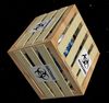
Here is the first part of the new model for the project. I kept the model simply, and will riley of LOD and bitmaps to fill the missing detail at distance. Each sub tile is 10m across, and can open upon 3 different axis?€™s (60 degrees off each other) Opening and closing these tiles is what creates the night and day (24hrs cycle) for a Blue Venus.
Each tile has a surface area of 84m^2 but is only 0.0125m (12.5cm or ~0.5 inches) thick
The total amount of light that can be blocked is >99%
The total amount of light that can be let though is >97%
(The 2% difference is do to the super structure)


BlueVenus_Sub_Tile.zip
The next part is to create the Standard Tile which is 1000m (1km) in size, then the Super Tile which is 100,000 m (100km) in size, and then finally the over all Parasol and Reflector.
I would appreciate it if someone would map the image. (I suck at it and I don't have any tools installed to do it anyway.) Place some good looking textures on it, nothing fancy, just enough to distinguish the parts. This will then become one of the bitmaps for next LOD.
If anyone has any questions, thoughts, general feedback.
Thanks
-Matt-
Enhancements for Celestia
http://www.celestiamotherlode.net/
http://www.celestialmatters.org/
Development Road Map
http://en.wikibooks.org/wiki/Celestia/D ... t_Road_Map
http://www.celestiamotherlode.net/
http://www.celestialmatters.org/
Development Road Map
http://en.wikibooks.org/wiki/Celestia/D ... t_Road_Map
-
ElChristou
- Developer
- Posts: 3776
- Joined: 04.02.2005
- With us: 20 years 2 months
Matt, as far as I know, Celestia unfortunately don't use LOD on models (just on the planet's spheres).
So what you are proposing despite being very interesting (and now yes I see why the whole geometry would be ideal) seems not really realist in the present version of the soft or perhaps only for high end configs.
Also what is missing actually in Celestia and is crucial for such addon in the casting of shadows by models (perso I would find a nonsense to not see on the planet the result in the change of luminosity...).
Now if you still want to show something on most config, the only way I see would be to use different textures for you base tile with different opacity; then you would have to script the opening and closing by loading the textures (different versions of the whole model) during a reduced laps of time from completely opaque to 99 transparent and vice versa.
This would at the distance give the right impression, but of course at closed range that won't be what you are proposing now...
This is why I was looking into faking it and only showing certain areas of the model, mainly the control nodes. The sub tile would be background for the large object. I know the object can be optimized even further, I added some extra non critical stuff. At a distance a simple image of the front and back should work. We could use the higher LOD mod for the first few rows, and then change them over to a simple 2d plane, or that?€™s what I was thinking.
Maybe Chris could implement an invisible object that can cast shadows and/or reduced opacity. Interestingly enough what would be required in addition would be to create a temporary light for the far side of the planet for the reflector.
Creating a script to dynamically change the shadow is something that I would like implement but is at the end of the list.
Extra stuff on model that could be removed to simplify the mesh:
Lattice joints. (Made a boo boo. The joints should have indentation, not an outward bulge. This is to allow easy access to the bolts that join the sections. I have updated the model.
Raised Reflectors/Solar Cells
Power/Gear box

I updated the model.
BlueVenus_Sub_Tile.zip
Enhancements for Celestia
http://www.celestiamotherlode.net/
http://www.celestialmatters.org/
Development Road Map
http://en.wikibooks.org/wiki/Celestia/D ... t_Road_Map
http://www.celestiamotherlode.net/
http://www.celestialmatters.org/
Development Road Map
http://en.wikibooks.org/wiki/Celestia/D ... t_Road_Map
-
chris
- Site Admin
- Posts: 4211
- Joined: 28.01.2002
- With us: 23 years 2 months
- Location: Seattle, Washington, USA
MKruer wrote:Maybe Chris could implement an invisible object that can cast shadows and/or reduced opacity. Interestingly enough what would be required in addition would be to create a temporary light for the far side of the planet for the reflector.
My plan is to implement proper shadowing. It's a lot of work, but very important for visual fidelity.
--Chris
Can someone check my work?
Venus receives roughly 192% sunlight per meter that Earth receives. This means that the Solar Parasol needs maintain a 48% blockage of sunlight to replicate the same illumination as Earth surface correct? There needs to be no more then 6.25% sunlight leakage in order to replicate the illumination of the full moon.
Venus receives roughly 192% sunlight per meter that Earth receives. This means that the Solar Parasol needs maintain a 48% blockage of sunlight to replicate the same illumination as Earth surface correct? There needs to be no more then 6.25% sunlight leakage in order to replicate the illumination of the full moon.
Enhancements for Celestia
http://www.celestiamotherlode.net/
http://www.celestialmatters.org/
Development Road Map
http://en.wikibooks.org/wiki/Celestia/D ... t_Road_Map
http://www.celestiamotherlode.net/
http://www.celestialmatters.org/
Development Road Map
http://en.wikibooks.org/wiki/Celestia/D ... t_Road_Map