
Greetings all!
after one broken computer and the consequent 'joy of self-build' experience, thought I should come up with a decent contribution to the Celestia forum before resuming my popping off of those witty comments.
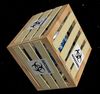
To that end, I have converted some of the released JAXA/SELENE (KAGUYA) topographic data (specifically, LALT-M) into an ASCII format CMOD, using the most inefficient but beautiful hand-crafted methods of production! I attach my permitted ration of three screenshots.
Let's see if this gets a reaction. If so, I have this packed up ready for Add On submission at the CM, but I'm still musing over the site's 'copyright licence' requirement.
Also, I really don't want to do any more Celestia models the 'hand-crafted' way, and am pondering how to crash course in doing it all by C++ or such, much analogous to t00fri's F-Tex tools stuff. Oh look, the beginning of another learning curve...
In addition, an idea I've been sitting on for a while: introducing an analogy to Virtual Textures' 'tiles', Celestia Models' 'foils'. I'll cryptically leave that at that for now.
Spiff.
Just a Test - Loon, A Partial Lunar Topographic Model.
-
Topic authorSpaceman Spiff
- Posts: 420
- Joined: 21.02.2002
- With us: 22 years 11 months
- Location: Darmstadt, Germany.
-
Chuft-Captain

- Posts: 1779
- Joined: 18.12.2005
- With us: 19 years 2 months
Re: Just a Test - Loon, A Partial Lunar Topographic Model.
Nice,
I don't suppose you've done the South Pole?
I'm toying with a Shackleton Base addon at the moment. -- A 25km diameter domed lunar city built inside Shackleton Crater:
(Inspired by an article in the Winter 2008 issue of Ad Astra - the magazine of the National Space Society).
This would look good nestled amongst a proper 3D terrain of all those craters.
"Is a planetary surface the right place for an expanding technological civilization?"
-- Gerard K. O'Neill (1969)
CATALOG SYNTAX HIGHLIGHTING TOOLS LAGRANGE POINTS
-- Gerard K. O'Neill (1969)
CATALOG SYNTAX HIGHLIGHTING TOOLS LAGRANGE POINTS
-
t00fri

- Developer
- Posts: 8772
- Joined: 29.03.2002
- Age: 22
- With us: 22 years 10 months
- Location: Hamburg, Germany
Re: Just a Test - Loon, A Partial Lunar Topographic Model.
Spiff,
Apparently there are JAXA/SELENE (KAGUYA) data available already. Can you specify what and where?
Thanks,
Fridger
Apparently there are JAXA/SELENE (KAGUYA) data available already. Can you specify what and where?
Thanks,
Fridger

-
Hungry4info

- Posts: 1133
- Joined: 11.09.2005
- With us: 19 years 5 months
- Location: Indiana, United States
Re: Just a Test - Loon, A Partial Lunar Topographic Model.
Pretty interesting work!
Current Setup:
Windows 7 64 bit. Celestia 1.6.0.
AMD Athlon Processor, 1.6 Ghz, 3 Gb RAM
ATI Radeon HD 3200 Graphics
Windows 7 64 bit. Celestia 1.6.0.
AMD Athlon Processor, 1.6 Ghz, 3 Gb RAM
ATI Radeon HD 3200 Graphics
-
t00fri
- Developer
- Posts: 8772
- Joined: 29.03.2002
- Age: 22
- With us: 22 years 10 months
- Location: Hamburg, Germany
Re: Just a Test - Loon, A Partial Lunar Topographic Model.
Spiff,
you wanted some provocative replies, didn't you?
OK. At this point, my feeling is that with your present resolution, normalmaps are FAR superior (and simpler) for rendering topographic data. Only when the observer's distance approaches the altitudes in question, do you really need genuine 3d modelling...
How does this sound?
Fridger
-
Topic authorSpaceman Spiff
- Posts: 420
- Joined: 21.02.2002
- With us: 22 years 11 months
- Location: Darmstadt, Germany.
Re: Just a Test - Loon, A Partial Lunar Topographic Model.
Sorry, no. That's covered by my "no more hand-crafting, want to do it by coding" get-out clause.Chuft-Captain wrote:I don't suppose you've done the South Pole?
The LALT_M data was complete and regularly sampled: it was the best to use for the test. The South Pole data has null points, and there is a 1km wide hole right at the pole. Still, your Shackleton Base add on will be an excellent way to cover that up - just don't forget the builders' rubble CMOD for the 'in fill'!
Yes. See http://wms.selene.jaxa.jp/selene_viewer/en/observation_mission/lalt/lalt_005.html. These are just 'tasters'. As far as I know, the full set will be released in Nov 2009. The sampling for LALT_M is 1/16? (1.9km). The sampling of the North and South Poles is 1/64? (in latitude only). Whether the sampling will be any finer than 1/64? (475m), I know not.t00fri wrote:Apparently there are JAXA/SELENE (KAGUYA) data available already. Can you specify what and where?
No, I wanted adulation!t00fri wrote:you wanted some provocative replies, didn't you?
Your comments are correct, but...t00fri wrote:At this point, my feeling is that with your present resolution, normalmaps are FAR superior (and simpler) for rendering topographic data. Only when the observer's distance approaches the altitudes in question, do you really need genuine 3d modelling...
At first sight, it might seem using models will supercede all that has gone before, making textures and normal maps obsolete. My understanding is that it is a common CG technique to use a normal map on models to provide a finer resolution 'bumpiness' than the meshes supply. I think Celestia does not do this yet.
In any case, I envisage a scheme where 'foils' are draped with matching 'tiles' in their own VT-like manner. Thus your F-Tex tools remain vital.
I think there is a common desire that Celestia will render planets as more than finely textured, yet smooth, spheres. Eventually, Celestia should render planets as models. However, one can already see some profile along the edge of the model where mountains exist. One day, we shall have our ground mode...
Spiff.
-
t00fri
- Developer
- Posts: 8772
- Joined: 29.03.2002
- Age: 22
- With us: 22 years 10 months
- Location: Hamburg, Germany
Re: Just a Test - Loon, A Partial Lunar Topographic Model.
I knew it, I knew it....Spaceman Spiff wrote:No, I wanted adulation!t00fri wrote:you wanted some provocative replies, didn't you?
Not at all, and in fact I am not worried that normalmaps might become obsoleteYour comments are correct, but...t00fri wrote:At this point, my feeling is that with your present resolution, normalmaps are FAR superior (and simpler) for rendering topographic data. Only when the observer's distance approaches the altitudes in question, do you really need genuine 3d modelling...
At first sight, it might seem using models will supercede all that has gone before, making textures and normal maps obsolete.
For now, Celestia essentially reaches its limits for planets/moons, when normalmaps cease to be adequate. This doesn't have to remain like so. Respective Google software shows impressively what can be done at this front!
ChrisL has actually experimented occasionally with normalmaps on models for certain asteroids. He used my nmtools if I correctly remember.My understanding is that it is a common CG technique to use a normal map on models to provide a finer resolution 'bumpiness' than the meshes supply. I think Celestia does not do this yet.
I think there is a common desire that Celestia will render planets as more than finely textured, yet smooth, spheres. Eventually, Celestia should render planets as models. However, one can already see some profile along the edge of the model where mountains exist. One day, we shall have our ground mode...
Spiff.
Sure, you have my total agreement. I would love it if at Dev more time could be spent to jointly experiment with such concepts, as well as with better atmospheres, better star renderings etc.
But...sometimes there are other constraints in life...
Fridger
-
Chuft-Captain
- Posts: 1779
- Joined: 18.12.2005
- With us: 19 years 2 months
Re: Just a Test - Loon, A Partial Lunar Topographic Model.
Unfortunately, there's a difference between the desire and the reality.Spaceman Spiff wrote:I think there is a common desire that Celestia will render planets as more than finely textured, yet smooth, spheres. Eventually, Celestia should render planets as models. However, one can already see some profile along the edge of the model where mountains exist. One day, we shall have our ground mode...
The reality of real-time 3D rendering is:
Hi-res textures are memory-intensive (will cause load delays on slow machines, but once in memory (assuming there's enough of it) will not greatly affect FPS.
Conversely, detailed 3D terrain requires the addition of huge numbers of polygons. The rendering of these is very much CPU/GPU bound, which means that the more polys you add, the worse your FPS becomes. This is unavoidable.
Don't get me wrong... I don't mean to discourage you from making these as I'd love to see some detailed 3D terrains, but unfortunately, this is just the fundamental reality.
If you're going to do this, then you'll need to find ways to optimize them in terms of polygon count.
EDIT:
At present VT's can only be used on Celestia's internal planetary meshes, but not on modeled .3DS or .CMOD meshes. I don't think Chris has any intention to change this in the future (there have been some discussions about this in the past). I think it's possibly quite a difficult problem to solve -- fitting VT tiles to irregular meshes.In any case, I envisage a scheme where 'foils' are draped with matching 'tiles' in their own VT-like manner.
CC
"Is a planetary surface the right place for an expanding technological civilization?"
-- Gerard K. O'Neill (1969)
CATALOG SYNTAX HIGHLIGHTING TOOLS LAGRANGE POINTS
-- Gerard K. O'Neill (1969)
CATALOG SYNTAX HIGHLIGHTING TOOLS LAGRANGE POINTS
-
chris
- Site Admin
- Posts: 4211
- Joined: 28.01.2002
- With us: 23 years
- Location: Seattle, Washington, USA
Re: Just a Test - Loon, A Partial Lunar Topographic Model.
Nice work, Spiff! I'm glad to see that people are already at work with the Kaguya data.
I've already begun work on a new sphere renderer that can handle elevation maps. The scheme used for rendering planets in 1.6.0 has one big drawback: one subdivision level is chosen for the entire planet. The new code does adaptive tessellation, with more triangles generated for regions of a planet closer to the viewer. This isn't a new idea--it's the usual way to handle terrain rendering, and Celestia is due for an update.
Adaptive tessellation has benefits even when an elevation map isn't used. Performance improves because less triangles need to be rendered, and perhaps more importantly, the new code fixes rendering caused by rendering very large triangles with a small near plane distance.
--Chris
-
Chuft-Captain
- Posts: 1779
- Joined: 18.12.2005
- With us: 19 years 2 months
Re: Just a Test - Loon, A Partial Lunar Topographic Model.
Good to hear!chris wrote:Nice work, Spiff! I'm glad to see that people are already at work with the Kaguya data.
I've already begun work on a new sphere renderer that can handle elevation maps. The scheme used for rendering planets in 1.6.0 has one big drawback: one subdivision level is chosen for the entire planet. The new code does adaptive tessellation, with more triangles generated for regions of a planet closer to the viewer. This isn't a new idea--it's the usual way to handle terrain rendering, and Celestia is due for an update.
Adaptive tessellation has benefits even when an elevation map isn't used. Performance improves because less triangles need to be rendered, and perhaps more importantly, the new code fixes rendering caused by rendering very large triangles with a small near plane distance.
--Chris
Will elevation maps and adaptive tessellation apply to only convex spherical meshes, or can it be made generic/flexible enough to allow terrain maps on/in spacecraft meshes.... ??
eg1. Shackleton Dome(flat reference surface)
eg2. O'Neill cylinders:
concave reference surface curved in 1 dimension (valleys),
or concave reference surface curved in 2 dimensions (endcaps)
CC
"Is a planetary surface the right place for an expanding technological civilization?"
-- Gerard K. O'Neill (1969)
CATALOG SYNTAX HIGHLIGHTING TOOLS LAGRANGE POINTS
-- Gerard K. O'Neill (1969)
CATALOG SYNTAX HIGHLIGHTING TOOLS LAGRANGE POINTS
-
Chuft-Captain
- Posts: 1779
- Joined: 18.12.2005
- With us: 19 years 2 months
Re: Just a Test - Loon, A Partial Lunar Topographic Model.
Chris,
Is it your plan to have terrain represented in a DEM data file? -- perhaps in the data directory and then generate the actual tessellated geometry in memory in real-time (where polygons are created with detail dependent on range, and only if in the FOV and not obscured by other geometry etc.).
If that's the plan, then it would also IMO be possible to apply various simple transformations eg concave spherical, concave cylindrical, convex spherical (the planetary case) to that geometry at the time of generation, to make it conform to various reference meshes such as the examples I mention above.
Of course in extreme situations concave reference meshes could present some interesting challenges wrt. elevated points crossing over each other's positions due to the curvature of the reference mesh.
CC
"Is a planetary surface the right place for an expanding technological civilization?"
-- Gerard K. O'Neill (1969)
CATALOG SYNTAX HIGHLIGHTING TOOLS LAGRANGE POINTS
-- Gerard K. O'Neill (1969)
CATALOG SYNTAX HIGHLIGHTING TOOLS LAGRANGE POINTS
-
Topic authorSpaceman Spiff
- Posts: 420
- Joined: 21.02.2002
- With us: 22 years 11 months
- Location: Darmstadt, Germany.
Re: Just a Test - Loon, A Partial Lunar Topographic Model.
I want to upload my add on to the CM first before resuming discussion of the main issue. Therefore I digress into add on copyright/licence issues. I tried uploading the add on to CM yesterday (for the first time in years!). The upload forms present me with a conundrum: what copyright and licence? I understand the need to uphold add on authenticity, but the form presented no obvious choices, as if one is supposed to know in advance. I feel like I'm to swear some legal oath but am lost on what it should be.
Here's the data source background I'm working to (from the draft readme.txt of the add on).
Therefore, credits should suffice, right?
This is analogous to john Van Vliet deriving his VT from Clementine data. I see JvV put 'cc' for the licence (Creative Commons, right?), so is assuming total copyright while crediting Clementine. Still, there are different CC licences, aren't there?
So, the entire copyright for the add on is mine, right? But which licence? What do people think?
Spiff.
Here's the data source background I'm working to (from the draft readme.txt of the add on).
As far as I understand, while that data is (c) JAXA/SELENE, this add on is not (c) JAXA/SELENE as a result: it's a derived work, right?Loon Add On readme.txt Draft wrote:Code: Select all
Data Sources
------------

   The textures were derived from the Level 2 tile tx_4_1.png of John van Vliet's 16K VT moon texture downloaded from the Celestia Motherlode (http://www.celestiamotherload.net/creators/johnvanvliet/VT/MoonVT_level012.zip).

   The meshes' vertex positions and normals were computed from data downloaded from the JAXA/SELENE website:
   - Website: http://wms.selene.jaxa.jp/selene_viewer/en/observation_mission/lalt/lalt_005.html
   - Data source: http://wms.selene.jaxa.jp/selene_viewer/en/observation_mission/lalt/005/LALT_M.zip.
Therefore, credits should suffice, right?
Loon Add On readme.txt Draft wrote:Code: Select all
Credits
-------

   - Lunar Topographic DEM data: LALT-M, JAXA/SELENE.
   - Lunar textures: 32K Moon Surface Map VT, John van Vliet.
This is analogous to john Van Vliet deriving his VT from Clementine data. I see JvV put 'cc' for the licence (Creative Commons, right?), so is assuming total copyright while crediting Clementine. Still, there are different CC licences, aren't there?
So, the entire copyright for the add on is mine, right? But which licence? What do people think?
Spiff.
-
t00fri
- Developer
- Posts: 8772
- Joined: 29.03.2002
- Age: 22
- With us: 22 years 10 months
- Location: Hamburg, Germany
Re: Just a Test - Loon, A Partial Lunar Topographic Model.
Spiff,
while we would be happy if you had an interest joining our CelestialMatters (CM) community, the CM site is not a general upload site, unlike the Motherlode (ML). Did you perhaps mix up CM and ML? Both CM and ML are actually located on the ibiblio server.
http://www.ibiblio.org/index.html
As you can see, our CM site has made it to the top position among many...
We aim to present things we like and value, with a tendency towards science, art and space exploration Our site is devoted to publishing only highest quality, both graphically and astrophysically. Certainly Celestia's matters play an important role at CM.
Let me know if you really meant the CM. Our system with personal webspace etc works by invitation only and every (major) contribution that is to be published at the CM website will be peer reviewed, including our own. The CM hosts are on an equal footing: Christophe Campos, Runar Thorvaldsen and myself.
Oh, I almost forgot our mysterious Boss: Mona Lisa
The scope is set out in more detail here:
http://www.celestialmatters.org/?q=node/70
Many familiar characters are can be retrieved as members of the CM forum:
http://forum.celestialmatters.org/
Cheers,
Fridger
while we would be happy if you had an interest joining our CelestialMatters (CM) community, the CM site is not a general upload site, unlike the Motherlode (ML). Did you perhaps mix up CM and ML? Both CM and ML are actually located on the ibiblio server.
http://www.ibiblio.org/index.html
As you can see, our CM site has made it to the top position
We aim to present things we like and value, with a tendency towards science, art and space exploration Our site is devoted to publishing only highest quality, both graphically and astrophysically. Certainly Celestia's matters play an important role at CM.
Let me know if you really meant the CM. Our system with personal webspace etc works by invitation only and every (major) contribution that is to be published at the CM website will be peer reviewed, including our own. The CM hosts are on an equal footing: Christophe Campos, Runar Thorvaldsen and myself.
Oh, I almost forgot our mysterious Boss: Mona Lisa
The scope is set out in more detail here:
http://www.celestialmatters.org/?q=node/70
Many familiar characters are can be retrieved as members of the CM forum:
http://forum.celestialmatters.org/
Cheers,
Fridger
-
chris
- Site Admin
- Posts: 4211
- Joined: 28.01.2002
- With us: 23 years
- Location: Seattle, Washington, USA
Re: Just a Test - Loon, A Partial Lunar Topographic Model.
Chuft-Captain wrote:Chris,
Is it your plan to have terrain represented in a DEM data file? -- perhaps in the data directory and then generate the actual tessellated geometry in memory in real-time (where polygons are created with detail dependent on range, and only if in the FOV and not obscured by other geometry etc.).
The terrain is represented by a two dimensional array of height values, stored in a hierarchical arrangement. The geometry patches are generated using the height map and tessellated in real time.
If that's the plan, then it would also IMO be possible to apply various simple transformations eg concave spherical, concave cylindrical, convex spherical (the planetary case) to that geometry at the time of generation, to make it conform to various reference meshes such as the examples I mention above.
Of course in extreme situations concave reference meshes could present some interesting challenges wrt. elevated points crossing over each other's positions due to the curvature of the reference mesh.
For the moment, I'm just using ellipsoids. Allowing for more general base geometry would make the code significantly more complicated.
--Chris
Re: Just a Test - Loon, A Partial Lunar Topographic Model.
Spiff,
Copyrights are complicated.
My understanding is that if you want to publish a derivative work, you first must have the permission of the copyright holders of the original work. Simply giving credit is not enough. Making your work available on a Web server is a form of publication.
Many of the images published by NASA are in the public domain, which means anyone can do whatever they want with them. In contrast, many of the images published by ESA are NOT in the public domain, and explicit, written permission must be obtained if you want to publish a derivative work. My guess is that this is at least partly because some member countries of ESA do not have the legal equivalent of public domain.
What you are allowed to do with the images published by JAXA is spelled out on their copyright page at http://jda.jaxa.jp/jda/service_e.html
My interpretation is that it's OK to use their images for educational purposes. If I were using them, I'd include a statement in a document included in the Addon which references their copyright page, perhaps even including a copy of the paragraph which gives permission. I'd also limit the license given to users of the Addon to only non-commercial, educational uses. However, I am not a lawyer. The laws of your country may be different.
Selden
-
Chuft-Captain
- Posts: 1779
- Joined: 18.12.2005
- With us: 19 years 2 months
Re: Just a Test - Loon, A Partial Lunar Topographic Model.
That sounds a little different to a standard DEM.chris wrote:The terrain is represented by a two dimensional array of height values, stored in a hierarchical arrangement. The geometry patches are generated using the height map and tessellated in real time.
As I understand it, a typical DEM is effectively the same as a grayscale image (where the level of grey represents the height value), which means that theoretically (if you allowed for it) we could just use greyscale images as DEM's which would give possibilities of defining and manipulating the terrain using standard image-editing software. (I can imagine that this principle theoretically could be extended to allow the use of full-color imagery as input DEM's which could allow other attributes of the mesh to be defined by the additional color channels.)
Can you elaborate at all on the nature of the hierarchical arrangement, and the reasoning behind it ? -- (perhaps referring to a simple example)? It seems that this proprietary requirement might limit the possibilities for manipulation with software as I suggest above.
I would assume that you would be using vector math to transform the height values firstly into the positions of vertices, and then to add tesselated vertices.chris wrote:For the moment, I'm just using ellipsoids. Allowing for more general base geometry would make the code significantly more complicated.If that's the plan, then it would also IMO be possible to apply various simple transformations eg concave spherical, concave cylindrical, convex spherical (the planetary case) to that geometry at the time of generation, to make it conform to various reference meshes such as the examples I mention above.
Of course in extreme situations concave reference meshes could present some interesting challenges wrt. elevated points crossing over each other's positions due to the curvature of the reference mesh.
If that's the case, then surely to "conform" to an ellipsoid (and in fact, any base geometry), just requires 1 further vector transformation (probably performed before the other transformations).
eg. Pseudo-code...
Code: Select all
tesselate( subdivision_level,
           subdivision_stddeviation,
           conformtobasegeometry(DEM, basegeometrytype, scalefactor)
          )
conformtobasegeometry() would return a set of vectors representing the DEM heights after being conformed to the base geometry, which would be further transformed by the tesselate function to give the final geometry.
basegeometrytype might include the attributes radius and originvector
If that's a reasonable representation of the conceptual model you're adopting, then I don't see how the other cases add significant complexity, as IMO the same architectural complexity is required for the ellipsoid case, as for the other geometries. The other cases would just require overrides of the conformtobasegeometry() function.
Each override would treat the orientation of the DEM and the direction of it's normals relative to the origin differently (and hence the direction of the vector operations) depending on the base geometry.
I guess there's some other factors to do with existing code/methods and other rendering issues that I'm not aware of which causes the additional complexity you refer to, but anyway, these are just a few thoughts based on my limited knowledge.
At the end of the day, whatever approach you take, as long as the different transformations (conform, DEM-offset, tesselate) are logically separated, the code should be readily extensible to the other geometries in the future.
CC
EDIT: Chris, I don't know if you ever saw my post about a guy called Eric Bruneton who did some interesting work on procedural terrain generation (although not in real-time). Anyway, if you didn't see my original post, here's a link to his "making of" pdf, which has some limited details on the techniques he used for rendering right triangulated irregular meshes: http://ebruneton.free.fr/rama3/rama.pdf
(may or may not be helpful/relevant.)
"Is a planetary surface the right place for an expanding technological civilization?"
-- Gerard K. O'Neill (1969)
CATALOG SYNTAX HIGHLIGHTING TOOLS LAGRANGE POINTS
-- Gerard K. O'Neill (1969)
CATALOG SYNTAX HIGHLIGHTING TOOLS LAGRANGE POINTS
-
chris
- Site Admin
- Posts: 4211
- Joined: 28.01.2002
- With us: 23 years
- Location: Seattle, Washington, USA
Re: Just a Test - Loon, A Partial Lunar Topographic Model.
Chuft-Captain wrote:That sounds a little different to a standard DEM.chris wrote:The terrain is represented by a two dimensional array of height values, stored in a hierarchical arrangement. The geometry patches are generated using the height map and tessellated in real time.
As I understand it, a typical DEM is effectively the same as a grayscale image (where the level of grey represents the height value), which means that theoretically (if you allowed for it) we could just use greyscale images as DEM's which would give possibilities of defining and manipulating the terrain using standard image-editing software. (I can imagine that this principle theoretically could be extended to allow the use of full-color imagery as input DEM's which could allow other attributes of the mesh to be defined by the additional color channels.)
Can you elaborate at all on the nature of the hierarchical arrangement, and the reasoning behind it ? -- (perhaps referring to a simple example)? It seems that this proprietary requirement might limit the possibilities for manipulation with software as I suggest above.
Some sort of hierarchical arrangement is necessary if you want to use large sets of topographic data. You only want to load the sections of the file that are in view and have the appropriate level of detail (i.e. if you're in low Earth orbit, you don't need 1m height data.) Preprocessing raw DEM files (or PNGs, or some other format) can dramatically improve performance for interactive terrain rendering. I'm just getting started with this, and at the moment I'm focusing on adaptive subdivision of smooth spheres and improving virtual texture performance. I'll certainly be doing more research and asking for input on how best to support terrain maps.
Yes there are... The tricky part of all of this isn't displacing vertices, it's the adaptive tessellation of the surface. For that, you need to be able to calculate two things: 1) the distance from the viewer to the surface, and 2) a bounding volume for a surface patch. For spheres, this isn't difficult; for ellipsoids, it's a bit harder, but still manageable. The other interesting surface type would be a triangle mesh, but adaptive tessellation of an arbitrary mesh would require much more complex code than the restricted case of ellipsoids. Applying a height map to other parameterized surfaces like torii and cylinders is only useful in very specific cases. The extra effort required to support them doesn't seem justified to me. If you want to have a terrain map inside an O'Neill cylinder, why not just do this in your modeling software? Is adaptive tessellation and level of detail essential for your models?I would assume that you would be using vector math to transform the height values firstly into the positions of vertices, and then to add tesselated vertices.chris wrote:For the moment, I'm just using ellipsoids. Allowing for more general base geometry would make the code significantly more complicated.
If that's the case, then surely to "conform" to an ellipsoid (and in fact, any base geometry), just requires 1 further vector transformation (probably performed before the other transformations).
eg. Pseudo-code...Code: Select all
tesselate( subdivision_level,
           subdivision_stddeviation,
           conformtobasegeometry(DEM, basegeometrytype, scalefactor)
          )
conformtobasegeometry() would return a set of vectors representing the DEM heights after being conformed to the base geometry, which would be further transformed by the tesselate function to give the final geometry.
basegeometrytype might include the attributes radius and originvector
If that's a reasonable representation of the conceptual model you're adopting, then I don't see how the other cases add significant complexity, as IMO the same architectural complexity is required for the ellipsoid case, as for the other geometries. The other cases would just require overrides of the conformtobasegeometry() function.
Each override would treat the orientation of the DEM and the direction of it's normals relative to the origin differently (and hence the direction of the vector operations) depending on the base geometry.
I guess there's some other factors to do with existing code/methods and other rendering issues that I'm not aware of which causes the additional complexity you refer to, but anyway, these are just a few thoughts based on my limited knowledge.
--Chris
-
Chuft-Captain
- Posts: 1779
- Joined: 18.12.2005
- With us: 19 years 2 months
Re: Just a Test - Loon, A Partial Lunar Topographic Model.
Are you thinking along the lines of "virtual DEM's"? -- (analogous to virtual textures with the same sort of folder structure ( level0, level1, ... etc )chris wrote:Some sort of hierarchical arrangement is necessary if you want to use large sets of topographic data. You only want to load the sections of the file that are in view and have the appropriate level of detail (i.e. if you're in low Earth orbit, you don't need 1m height data.) Preprocessing raw DEM files (or PNGs, or some other format) can dramatically improve performance for interactive terrain rendering. I'm just getting started with this, and at the moment I'm focusing on adaptive subdivision of smooth spheres and improving virtual texture performance. I'll certainly be doing more research and asking for input on how best to support terrain maps.
My thoughts on this would be that the actual distance from the viewer is not the key issue, but rather the relation between polygon size and distance (ie. apparent polygon size) -- The decision as to whether to further sub-divide or not depends on the angle subtended by the polygon from the observer's viewpoint. EDIT: I expect that a 200m sized feature observed from 1km distance would receive the same level of detail as a 20km sized feature observed from 100km (assuming the same FOV). Would you agree?chris wrote:... The tricky part of all of this isn't displacing vertices, it's the adaptive tessellation of the surface. For that, you need to be able to calculate two things: 1) the distance from the viewer to the surface, and 2) a bounding volume for a surface patch.
eg....some more pseudo-code...
Code: Select all
for p in all-polygons-in-FOV
{
   if angle-subtended-by-polygon( p, observer ) > some-threshold-theta
   {
      subdivide( p )
   }
}
This means that the amount of tessellation/subdivision would also increase if you used the ',' key to zoom in to an object, without actually changing the distance.
(Just one other thought...It might be quite a good idea to allow the degree and/or threshold of tessellation to be configurable in celestia.cfg)
Sorry, perhaps a misunderstanding. I wasn't trying to suggest doing this for complex irregular meshes, but rather a limited set of "simply defined mathematical curves". ie. A way of telling the "convolve" function where the center of the base geometry is, which way to orient the normals, which direction(s) to "bend" the terrain, and by how much (ie. what's the radius of the curve).chris wrote:For spheres, this isn't difficult; for ellipsoids, it's a bit harder, but still manageable. The other interesting surface type would be a triangle mesh, but adaptive tessellation of an arbitrary mesh would require much more complex code than the restricted case of ellipsoids. Applying a height map to other parameterized surfaces like torii and cylinders is only useful in very specific cases. The extra effort required to support them doesn't seem justified to me.
In this sense, putting the terrain on the inside of a concave sphere is just the reverse of putting it on the outside of a convex one (the simple planetary case), and IMHO is EDIT: only slightly more complex as it's just a matter of performing the vector transformations in a different direction and recognizing that the mesh normals are reversed.
A cylindrical curve is just a simplified version of the spherical curve, with curvature in 1 dimension, and flat in the other direction.
I hadn't considered a torus, which I agree would be somewhat more complex, requiring 2 different radii of curvature. (although you could argue it's just the same as the sphere but with a smaller radius of curvature in one of the 2 dimensions.
I'm not suggesting you create a whole lot of complex code to handle all these geometries in the first iteration, just that you take the possibilities into consideration in the design of your code so that it's easily extensible.
Thinking of base geometries in terms of how they are defined as origins and curves in mathematical/spatial terms rather than specific shapes or meshes, and incorporating this principle into your design, will I think facilitate this.
I think the number of polys in the current design of the O'Neills is already pushing the performance of 88 series cards, so I think in the long-term that it will become impossible to add any level of detailed terrain without some form of adaptive sub-division.chris wrote:If you want to have a terrain map inside an O'Neill cylinder, why not just do this in your modeling software? Is adaptive tessellation and level of detail essential for your models?
To be honest, in this context, I would be happy in the short/medium term, with an easy way to conform a DEM or DEMs to the underlying geometry, even without adaptive tessellation. (Some compromises in the # of vertices would just have be made)
However, once the observer gets down into the terrain at ground level and starts travelling through it, I think this is when it becomes necessary in the long-term to have some form of adaptive tessellation as well, because the number of vertices you'd need to make the terrain appear realistic at close range, would make it un-usable in terms of frame-rate because ALL those poly's would have to be rendered, even if 20 km away in the distance.
Have a look at Eric Bruneton's RAMA video HERE to see what I'm on about. (It's well worth the 88MB download
CC
"Is a planetary surface the right place for an expanding technological civilization?"
-- Gerard K. O'Neill (1969)
CATALOG SYNTAX HIGHLIGHTING TOOLS LAGRANGE POINTS
-- Gerard K. O'Neill (1969)
CATALOG SYNTAX HIGHLIGHTING TOOLS LAGRANGE POINTS
-
chris
- Site Admin
- Posts: 4211
- Joined: 28.01.2002
- With us: 23 years
- Location: Seattle, Washington, USA
Re: Just a Test - Loon, A Partial Lunar Topographic Model.
Chuft-Captain wrote:Are you thinking along the lines of "virtual DEM's"? -- (analogous to virtual textures with the same sort of folder structure ( level0, level1, ... etc )chris wrote:Some sort of hierarchical arrangement is necessary if you want to use large sets of topographic data. You only want to load the sections of the file that are in view and have the appropriate level of detail (i.e. if you're in low Earth orbit, you don't need 1m height data.) Preprocessing raw DEM files (or PNGs, or some other format) can dramatically improve performance for interactive terrain rendering. I'm just getting started with this, and at the moment I'm focusing on adaptive subdivision of smooth spheres and improving virtual texture performance. I'll certainly be doing more research and asking for input on how best to support terrain maps.
Yes, something like that.
Yes, of course the apparent size of the surface patches is how the subdivision level should be determined. However, the fundamental properties are still the ones I listed: distance and bounding volume (i.e. approximate size.) Field of view must be considered, but it's not a fundamental property of the geometry.My thoughts on this would be that the actual distance from the viewer is not the key issue, but rather the relation between polygon size and distance (ie. apparent polygon size) -- The decision as to whether to further sub-divide or not depends on the angle subtended by the polygon from the observer's viewpoint. EDIT: I expect that a 200m sized feature observed from 1km distance would receive the same level of detail as a 20km sized feature observed from 100km (assuming the same FOV). Would you agree?chris wrote:... The tricky part of all of this isn't displacing vertices, it's the adaptive tessellation of the surface. For that, you need to be able to calculate two things: 1) the distance from the viewer to the surface, and 2) a bounding volume for a surface patch.
A cylinder is an ellipsoid with two equal, finite axes and one infinite one. Yet in practical terms, extra effort is still necessary to support adaptive tessellation of a cylindrical terrain map. My point is that given very limited time, I'm not likely to invest it in writing special code that has no purpose beyond rendering objects that don't actually exist. This is not meant to discourage you or anyone else creating speculative add-ons, which I do think are interesting. But, you should try and find methods of showing rendering these objects that use the existing features of Celestia. My focus is on implementing and debugging the more general features of Celestia, not ones that are specific to a particular add-on.Sorry, perhaps a misunderstanding. I wasn't trying to suggest doing this for complex irregular meshes, but rather a limited set of "simply defined mathematical curves". ie. A way of telling the "convolve" function where the center of the base geometry is, which way to orient the normals, which direction(s) to "bend" the terrain, and by how much (ie. what's the radius of the curve).chris wrote:For spheres, this isn't difficult; for ellipsoids, it's a bit harder, but still manageable. The other interesting surface type would be a triangle mesh, but adaptive tessellation of an arbitrary mesh would require much more complex code than the restricted case of ellipsoids. Applying a height map to other parameterized surfaces like torii and cylinders is only useful in very specific cases. The extra effort required to support them doesn't seem justified to me.
In this sense, putting the terrain on the inside of a concave sphere is just the reverse of putting it on the outside of a convex one (the simple planetary case), and IMHO is EDIT: only slightly more complex as it's just a matter of performing the vector transformations in a different direction and recognizing that the mesh normals are reversed.
A cylindrical curve is just a simplified version of the spherical curve, with curvature in 1 dimension, and flat in the other direction.
I hadn't considered a torus, which I agree would be somewhat more complex, requiring 2 different radii of curvature. (although you could argue it's just the same as the sphere but with a smaller radius of curvature in one of the 2 dimensions.
I'm not suggesting you create a whole lot of complex code to handle all these geometries in the first iteration, just that you take the possibilities into consideration in the design of your code so that it's easily extensible.
Thinking of base geometries in terms of how they are defined as origins and curves in mathematical/spatial terms rather than specific shapes or meshes, and incorporating this principle into your design, will I think facilitate this.
I suspect that there are bottlenecks other than GPU geometry processing that are at fault--maybe inefficiencies in Celestia, or maybe your add-on.I think the number of polys in the current design of the O'Neills is already pushing the performance of 88 series cards, so I think in the long-term that it will become impossible to add any level of detailed terrain without some form of adaptive sub-division.chris wrote:If you want to have a terrain map inside an O'Neill cylinder, why not just do this in your modeling software? Is adaptive tessellation and level of detail essential for your models?
To be honest, in this context, I would be happy in the short/medium term, with an easy way to conform a DEM or DEMs to the underlying geometry, even without adaptive tessellation. (Some compromises in the # of vertices would just have be made)
You should write some tools to do this. Or search for some existing tools--I wouldn't be surprised if applications like Anim8or can apply a displacement map to a cylinder.
--Chris
Re: Just a Test - Loon, A Partial Lunar Topographic Model.
Sorry for the newbie question,but what is a DEM?