MINI TUTORIAL on 3D problems
Posted: 13.08.2005, 01:30
Hello Guys,
Here is a mini tutorial to illustrate some problems and solutions meet in a process of 3D modeling.
What is important to have in mind is that in a variety of case a bad use of some automated tools like Boolean operations or subdividing tools (tessellation) may have strong consequences in further operations, with sometimes resulting in a model full of bugs?€¦ and so useless.
Let?€™s begin.
I have chosen a part of the docking module (for ISS) of the shuttle.

Pict 1 : left view.
2 meshes will be merged; Pict 2 and 3 show how the two meshes are positioned.
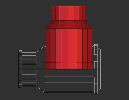
Pict 2
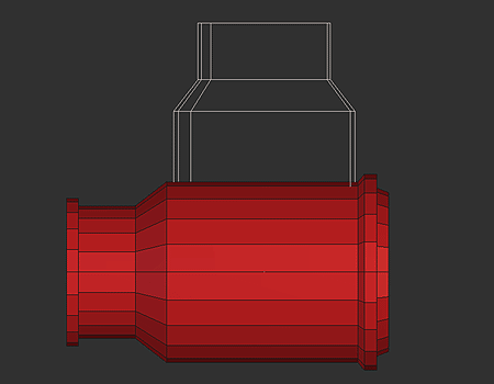
Pict 3
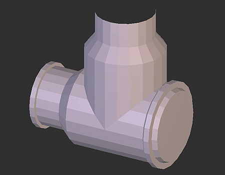
Pict 4 : a perspective view of the scene.
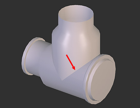
Pict 5 : OpenGL rendering: the red arrow shows the way the intersection of both meshes is rendered; as the 2 meshes are supposed to represent a single volume, this is not acceptable?€¦
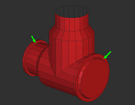
Pict 6 : the meshes have been merged with a Boolean addition. In the process note the two faces marked by green arrows; before the operation those faces were made of several little faces in a common plane. This is the reason why all those little faces have been merged in a single one.
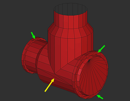
Pict 7 : here the faces with more than 4 points have been tessellated. Note the strange way the soft has done this in some part (green arrows). The solutions used by the soft are not always the better ones. Also note the tessellation of the zone pointed by the yellow arrow; later we will talk about this.
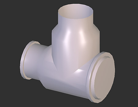
Pict 8 : OpenGL rendering: we can see several light artifacts not acceptable.
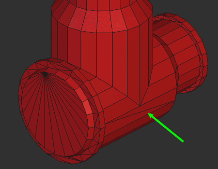
Pict 9 : Let?€™s have a look at the other side of the mesh; the tessellation of the zone pointed by the green arrow is not the same than the one in pict 7. Let?€™s have a closer look:
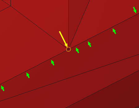
Pict 10 : Can you see the tiny perturbations (green arrows) on the line? Something is wrong. The point in the yellow circle is guilty:
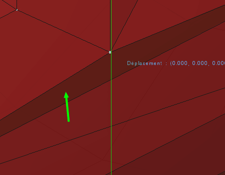
Pict 11 : Moving this point reveal an hidden poly (green arrow). This kind of things occurs when there is misplacement of meshes before making some operations. In this case, the misplacement was so tiny that the soft has done a good job a one side of the mesh but not on the other. This example is very frequent, and some big problems can appear later if this is not solved at time.
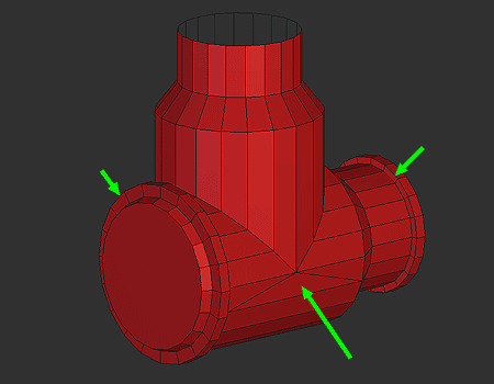
Pict 12: I have solved those little problems and also tessellate at my taste the 2 zones we have seen in pict 7.
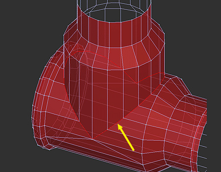
Pict 13 : As we need to smooth the intersection resulting of the addition of the primary meshes, we are going to create a bezel along the intersection. The yellow arrow shows the vertices forming the intersection.
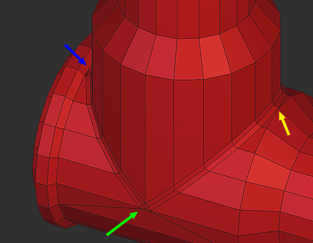
Pict 14 : result of the bezel tool; note the number of poly in the zone pointed by the green arrow, the yellow arrow point to 2 points very close; later those ones will be merged. The blue arrow point to a zone where the bezel is not so neat?€¦ later (once more) we will see this closer.
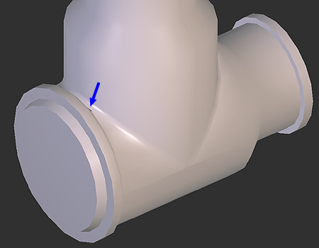
Pict 15 : OpenGL rendering: things look quite good but we can note some strange shadows, and a default (blue arrow); let?€™s have a look:
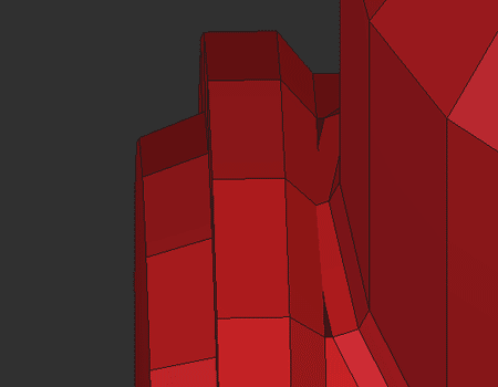
Pict 16 : Wrong geometry due to the action of the bezel. Later we will solve this.
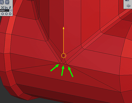
Pict 17 : We will modify by hand some vertices, to optimize the mesh.
Remember in Pict 14 the green arrow? Here we can see some vertices have already been merged. The point in the yellow circle has been moved; see the next pict:
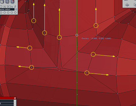
Pict 18 : All points of the bezel have been moved?€¦
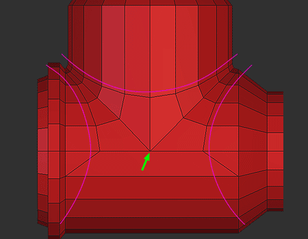
Pict 19 : Note the way those points are now following a virtual curve. Finally all points in the zone pointed by the green arrows were merged.
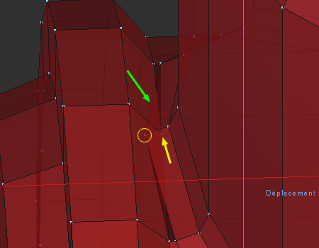
Pict 20 : Note the way some faces are badly positioned (green arrow). The point in the yellow circle will be merged with the one pointed with the yellow arrow. This more some others little manipulation will solve the problem in this zone.
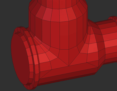
Pict 21 : Final result for this example, the mesh is now optimized; few poly, good result; see last pict:
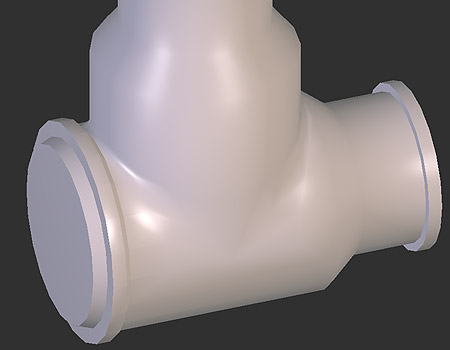
Pict 22 : OpenGL rendering: no more ugly shadows.
To resume:
Good 3D is not the simple use of funny tools (Boolean operations, bezel, tessellation, distorch boxes, etc) but pass through a real knowledge of the topography of the meshes and a deep knowledge of the tools (lot of them have strong defaults). Working at the vertices level can scare some people, but it?€™s the best way to understand 3D and avoid some problem witch can result in the lost of the model.
More Mini Tutorial later.
Here is a mini tutorial to illustrate some problems and solutions meet in a process of 3D modeling.
What is important to have in mind is that in a variety of case a bad use of some automated tools like Boolean operations or subdividing tools (tessellation) may have strong consequences in further operations, with sometimes resulting in a model full of bugs?€¦ and so useless.
Let?€™s begin.
I have chosen a part of the docking module (for ISS) of the shuttle.

Pict 1 : left view.
2 meshes will be merged; Pict 2 and 3 show how the two meshes are positioned.

Pict 2

Pict 3

Pict 4 : a perspective view of the scene.

Pict 5 : OpenGL rendering: the red arrow shows the way the intersection of both meshes is rendered; as the 2 meshes are supposed to represent a single volume, this is not acceptable?€¦

Pict 6 : the meshes have been merged with a Boolean addition. In the process note the two faces marked by green arrows; before the operation those faces were made of several little faces in a common plane. This is the reason why all those little faces have been merged in a single one.

Pict 7 : here the faces with more than 4 points have been tessellated. Note the strange way the soft has done this in some part (green arrows). The solutions used by the soft are not always the better ones. Also note the tessellation of the zone pointed by the yellow arrow; later we will talk about this.

Pict 8 : OpenGL rendering: we can see several light artifacts not acceptable.

Pict 9 : Let?€™s have a look at the other side of the mesh; the tessellation of the zone pointed by the green arrow is not the same than the one in pict 7. Let?€™s have a closer look:

Pict 10 : Can you see the tiny perturbations (green arrows) on the line? Something is wrong. The point in the yellow circle is guilty:

Pict 11 : Moving this point reveal an hidden poly (green arrow). This kind of things occurs when there is misplacement of meshes before making some operations. In this case, the misplacement was so tiny that the soft has done a good job a one side of the mesh but not on the other. This example is very frequent, and some big problems can appear later if this is not solved at time.

Pict 12: I have solved those little problems and also tessellate at my taste the 2 zones we have seen in pict 7.

Pict 13 : As we need to smooth the intersection resulting of the addition of the primary meshes, we are going to create a bezel along the intersection. The yellow arrow shows the vertices forming the intersection.

Pict 14 : result of the bezel tool; note the number of poly in the zone pointed by the green arrow, the yellow arrow point to 2 points very close; later those ones will be merged. The blue arrow point to a zone where the bezel is not so neat?€¦ later (once more) we will see this closer.

Pict 15 : OpenGL rendering: things look quite good but we can note some strange shadows, and a default (blue arrow); let?€™s have a look:

Pict 16 : Wrong geometry due to the action of the bezel. Later we will solve this.

Pict 17 : We will modify by hand some vertices, to optimize the mesh.
Remember in Pict 14 the green arrow? Here we can see some vertices have already been merged. The point in the yellow circle has been moved; see the next pict:

Pict 18 : All points of the bezel have been moved?€¦

Pict 19 : Note the way those points are now following a virtual curve. Finally all points in the zone pointed by the green arrows were merged.

Pict 20 : Note the way some faces are badly positioned (green arrow). The point in the yellow circle will be merged with the one pointed with the yellow arrow. This more some others little manipulation will solve the problem in this zone.

Pict 21 : Final result for this example, the mesh is now optimized; few poly, good result; see last pict:

Pict 22 : OpenGL rendering: no more ugly shadows.
To resume:
Good 3D is not the simple use of funny tools (Boolean operations, bezel, tessellation, distorch boxes, etc) but pass through a real knowledge of the topography of the meshes and a deep knowledge of the tools (lot of them have strong defaults). Working at the vertices level can scare some people, but it?€™s the best way to understand 3D and avoid some problem witch can result in the lost of the model.
More Mini Tutorial later.